CAD
Week 1
For this week’s blog, the main thing that we will be going through are
CADD refresher
CADD Refresher
Before we use CAD, we need to understand why we are using CAD and how it is useful for our chemical design journey. Computer aided design software helps users create their designs in either 2D or 3D so that we are able to visualize our own concepts. It enables the development, modification and optimization of the whole design process making it more efficient.
In order to recap what I have learned in the last semester, I have decided to redo the keychain to hone my skills and get familiar with fusion 360 to prepare me for more complex objects.
1.Firstly we will start with a brand new project for the personalized keychain.

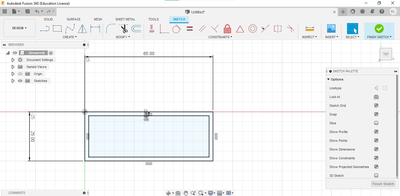
2.After that we will start by creating a sketch and selecting a plane. We will create a rectangle the size of 65mm by 25mm.

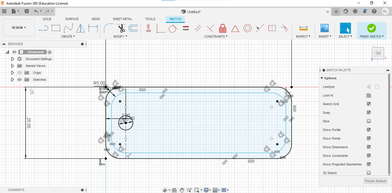
3.After that we will use the offset tool and click on the rectangle and offset the sketch by 2mm
4.We will then use the fillet tool to fillet the 4 corners to make it rounded. Change the radius value of the fillet tool to 5mm for the 4 corners.

5.We will add a line towards the end of one side and make it into a construction line.

6.For the next stop, we will use a dimension tool and click on the line that we just created and the left hand edge line and ensure that there is a space of 7mm between both lines.

7.We will then create a point on the line and sketch a 5mm circle on the same point
8.We will create text and place it on the right of the construction line and type your name and choose your desired font.

9.After this we will finish the sketch by pressing the finish sketch button on the top right hand corner. We will extrude the base without the hole by 3mm.

10.After that, we will hide all the bodies and only allow the sketches to appear. We will then select the name and the border and extrude them by 1.5mm.After that, from the extrude menu, we will select the offset plane and offset it by 3mm.Hide the sketch and you will see something like the picture below.

You can play around and take a look at the final product down below.
Week 2
How to design an F1 Phone holder using CAD
This is just a rough guide to designing a phone holder. You can modify some parts of the instructions to make them suited for you. It doesn’t have to be followed accurately and most of it can be a rough approximation.
We will first design the main body of the car and the 2 wheels.
Step 1: We first need to open up Fusion 360 and select one of the planes
Step 2: Press modify from the tabs and select “change parameters”

Step 3: Click on the user parameters and add new parameters. You can choose to follow my dimensions or use your own dimensions.

Step 4:Click C on your keyboard to create a circle and start from the center. Key in Wheel into the measurement box and a circle of radius 200mm will appear
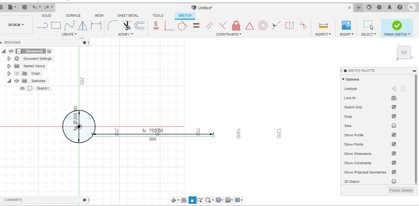
Step 5:Create a line and start from one point on the circle and type in Length for a line of 750mm to appear. Ensure that it is a straight line.

Step 6: Create a 2 point circle and start the first point on the other end of the line and type in Wheel. A circle with a radius of 200mm will appear. Ensure that both the circles on aligned.
Next, we will be designing the wing of the F1 Car

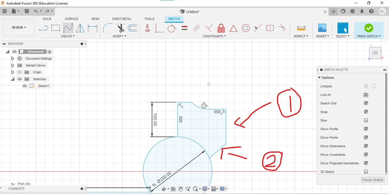
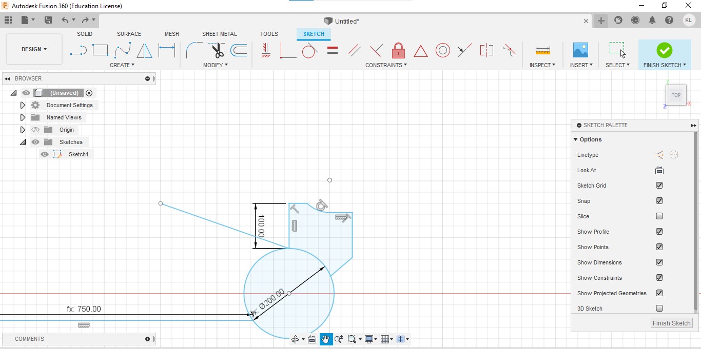
Step 7: Create a line with a length of 100mm from the top of the 2nd wheel.

Step 8:
(1) Connect another line perpendicular to the line created in step 7.
(2) Create another line 20mm below and 20mm away from the line.
(3) Use the tangent arc function and connect the two lines together.
Step 9:
(1) Create a line perpendicular to the 2nd line in step 8 and make it about 120mm long.
(2) Create a line from the end of the first line and connect it to the wheel at an angle.
Next we will create the top part of the car.
Step 10: From the top of the 2nd wheel, create a line and angle the line approximately 35° from the wheel and make it about 300mm.

Step 11:
(1) Create another line and start from the other end of the angled line. Make this line about 80mm long.
(2) Create a line perpendicular with a length of 10mm.

Step 12: Create an empty box 10mm by 10mm to make an air duct of an F1 car.
After that, you can create the monocoque based on how you want it to look and connect the lines to the top of the front wheel.
Next, we are going to create the front wing of the F1 car.

Step 13: Create a line that is aligned with the length and type in wing. A line with a length of 250mm will appear.
Step 14: At the end of that line, create another line that connects it to the front wheel at an angle of approximately 45°.
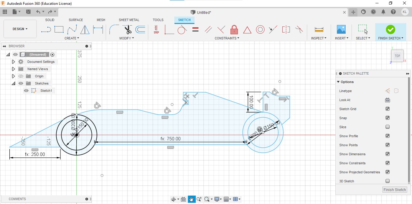
Step 15: Create a circle in the middle of both wheels and type rim. A circle of radius 150mm will appear.

Step 16: Press the finish sketch option and then extrude only the wheels of the car by 3mm.
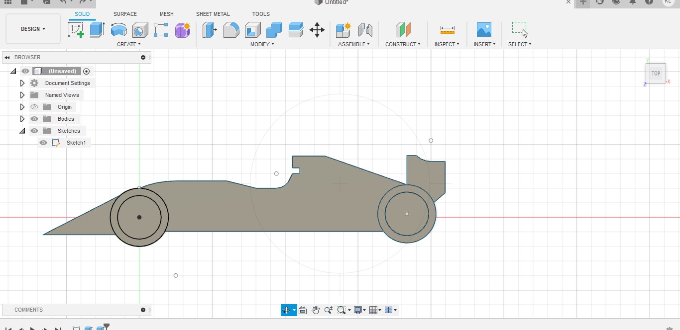
Step 17: Extrude the remaining part of the car by 1mm.

Step 18 (Optional):
Hide the bodies and create a small rectangle near the air duct.
Create a text to put your name/initials on it.
After that, extrude the text by 3mm.

It should look something like that afterward.

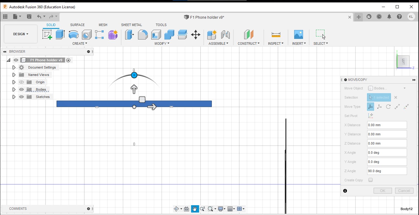
Step 19:Duplicate the part by clicking on the move/copy button and tick the copy part and move the part by 500mm.
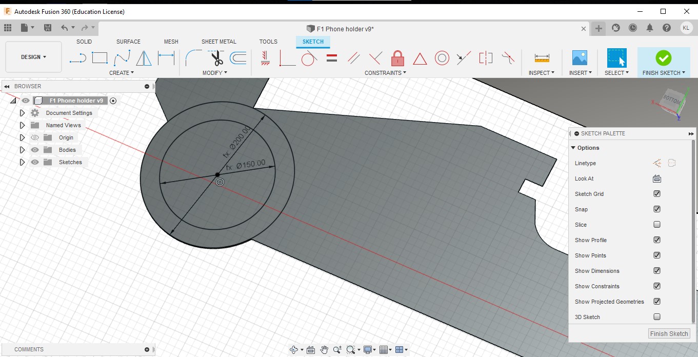
Step 20: Create a circle for the wheels and rims of both wheels of the duplicated part.

Inner facing
Outer facing
Step 21: Extrude the inner facing part by 2mm and the outer facing part by 2mm. This will give the car the 3D depth.
Step 22:
Create a sketch of a rectangle of 10mm by 500mm.
Extrude the sketch by 3mm.
Step 23: Using the move/copy button, align the cuboid to the air ducts of both parts.
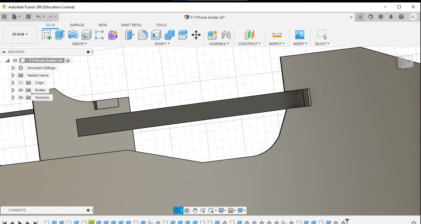
Next, we will create a part that holds both pieces together and also makes it look like an F1 Rear wing.
Step 24: Create a small gap of 3mm in depth and 30mm in length on both of the rear wings of the parts.

Step 25: Create a wing with a length of 516mm long and then have a catch at the ends of both side to ensure a secure fit with the gaps of the rear wings of both parts.

Step 26:Extrude the part by 30mm.

Step 27: Use the copy/move button to move the part and ensure that it is aligned w all 3 axes on the rear wing.
You are finally done!!
You have managed to create your own F1 phone holder.
This is just a rough guide on how to design an F1 phone holder. Depending on how you like to design it you can adjust the measurements and the angles to your liking.
There can be some improvement done such as making to front wing more rounded by perhaps using the fillet tool to make it more as
Since some of the parts are done using parametric design, the model can be adjusted to how you want it.
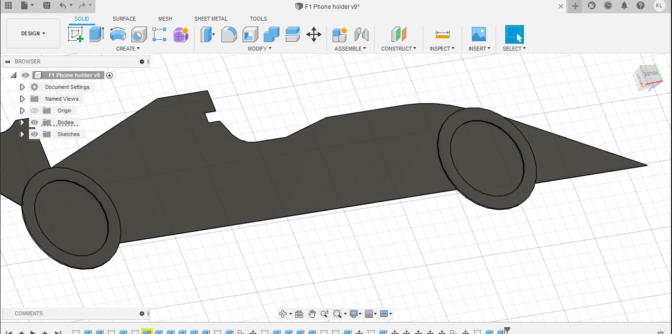
Below is the 3D model of the F1 phone stand. Feel free to take a look.
Reflection on Handphone holder
Designing this handphone holder was a challenge for me as I had to design it from scratch and there was nothing online for me to refer to. However, I have learned a lot from this experience as I watch Youtube videos during parts where I wasn't confident in doing. This allowed me to understand more functions in Fusion 360 and how to use it properly. It took me an entire weekend to complete this unique phone holder and I was quite happy with the end result.

Comments
Post a Comment