Project Development
Project development entry
For this blog entry, we are going to talk about:
Our chemical device
How our team planned, allocated the tasks, and executed the project.
Documentation of the entire design and build process our your chemical device
In charge of every part of the project
Documentation of individual contribution to this project
Links to page of teammates’ blog
Problems the team faced and how we overcome them
Our Team’s Chemical Device
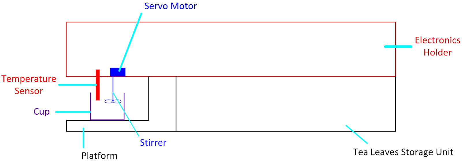
The chemical device that we have chosen is a Tea-maker.
The group worked on creating a tea maker. Our objective is to combine the heating and infusing process of brewing tea into a single machine which simplifies the tea preparation process.
For it to work, we would need a certain volume of water and a measured amount of tea leaves. The hot water would be poured on the tea leaves in a tea basket which allows the tea leaves to steep. Different tea has their own brewing requirements as each tea type has their own optimum brewing time and temperature.
Our tea maker should be cheap and easy to use as the current tea makers in the market are expensive and very complex which makes maintaining the tea maker a tedious process. Besides that our tea maker should also be able to steep the tea at the desired temperature within the desired amount of time.


Team Planning,Task allocation, and execution
My Team consists of 4 people. The 4 people are:
Nick
Kieran
Anwar
Xavier
In our task allocation, Nick was in charge of designing the tea maker, as well as producing the codes to be used, I was in charge of drawing the different parts to be 3D printed or laser cut in Fusion 360, Anwar was in charge of booking the different facilities and assembly of the final product, and lastly, Xavier was in charge of wiring the different components together.

In order to ensure that the group stays productive, we decided to use the Gantt chart to help us be more effective in doing our tasks to ensure that we are able to complete our individual tasks on time.
My individual contribution
I designed the multiple different components on the tea maker from scratch. Since I was not confident in doing the programming of the temperature sensor and the servo motor. I decided to do the designing of all the different parts that we need to produce our tea maker.The whole process of all the different parts were very tedious.However, after using Fusion for a long period of time,I better understand how to use it and I am also using a wider variety of tools to help me create my objects in Fusion.
Design and Build Process
Design and build of Tea Cup (Done by Kieran)

Documentation of Tea Cup
Step 1: In order to ensure that the tea cup is able to adapt to our fit in our tea maker,we designed our tea cup to be parametric.This allows us to adjust the radius and height of the cup based on our needs and makes small changes easier to edit. This is the parametric values that we have used for the height and radius of the tea cup.

Step 2: Create a new sketch and use the C button on the keyboard to sketch a circle and key in “teacup diameter”.This will set the diameter of the circle to be 60mm.

Step 3: Click on finish sketch

Step 4: Click the “E” key to enable the extrude tool. Extrude the sketch of the circle and key in teacup height. This will extrude the height of the circle to 40mm.
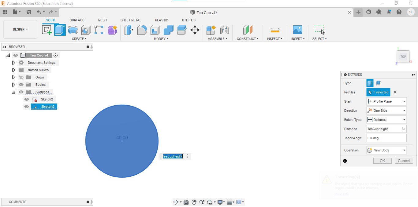
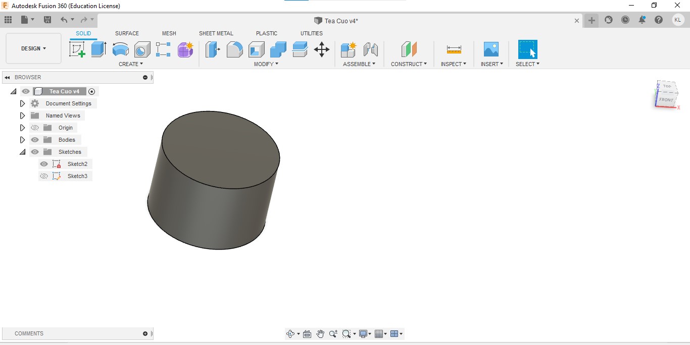
Step 5: After extruding the sketch of the circle, it should look something like a cylinder.
Step 6: Use the shell tool and click on the top face of the cylinder. Ensure that the inside thickness is 5mm.It should look like the picture below.

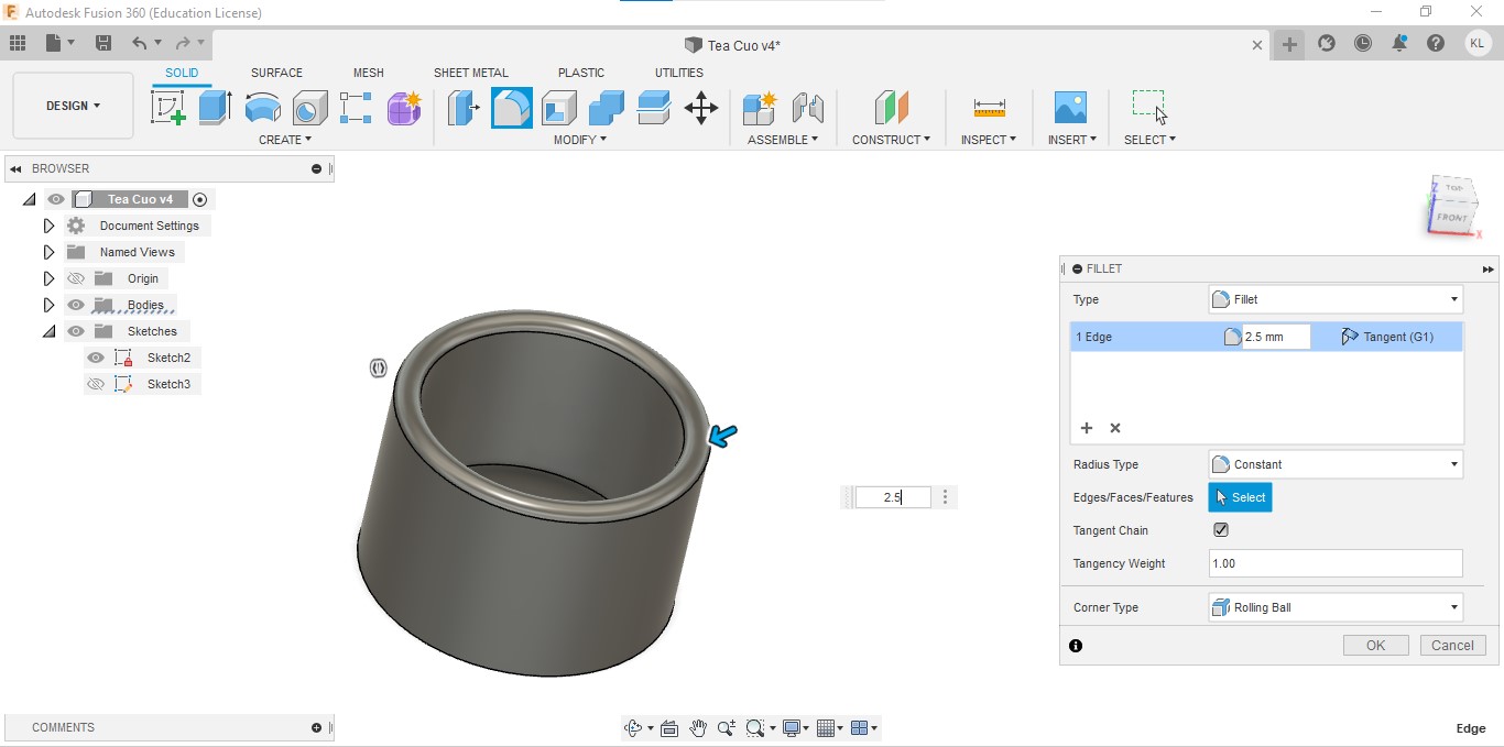
Step 7:Using the fillet tool, we are going to fillet the edge of the inner circle with a value of 2.5mm.

Step 8: We are going to repeat step 7 for the edge of the outer circle.
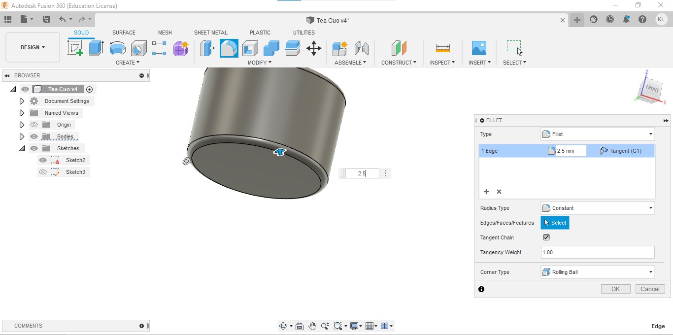
Step 9: In order to make the tea cup look nicer, we are going to fillet the bottom edge of the tea cup. I used a value of 2.5mm fillet at the edge. It should look something like the picture below.
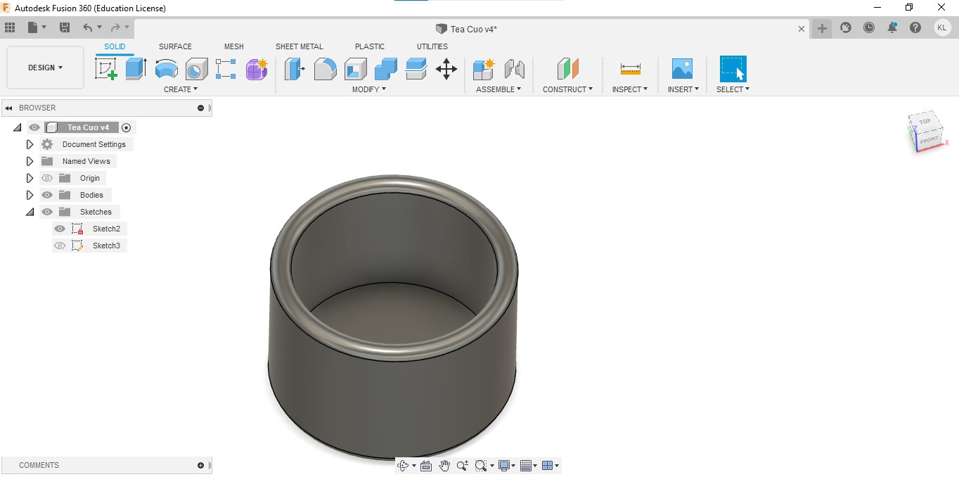
Step 10: This is the end product of the tea cup that we have designed.
Design and build of Tea Cup Holder (Done by Kieran)
Documentation of Tea Cup Holder

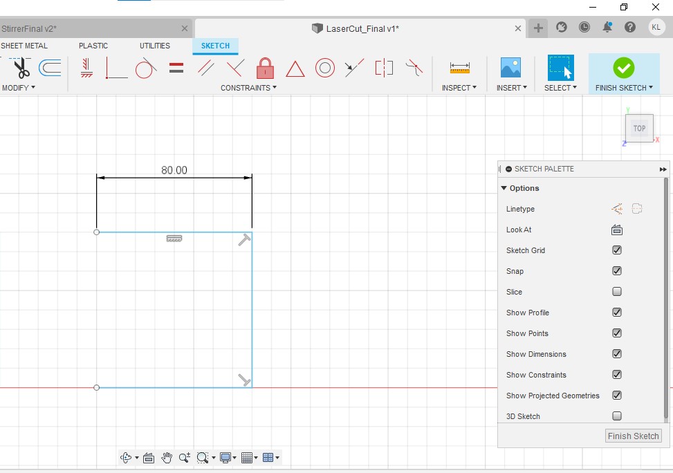
Step 1: Start a new sketch and enter “C” on the keyboard to sketch a circle.The circle should have a diameter of 80mm.

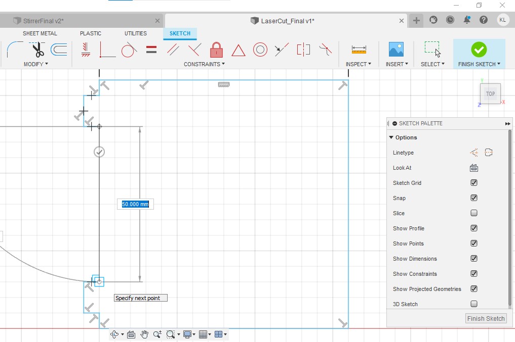
Step 2:At the top of the circle,create a line with a length of 50mm.
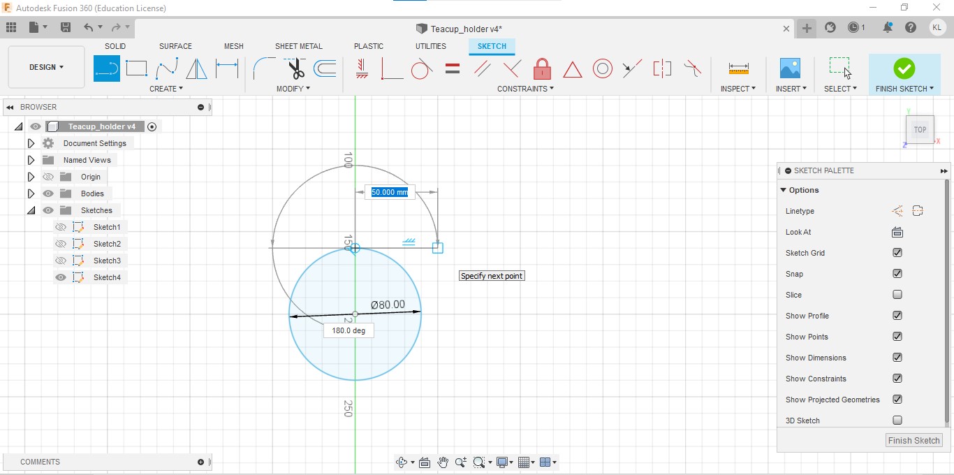
Step 3:Connect the line in step 2 with a new line with a length of 80mm.

Step 4:Connect the line in step 3 with the bottom of the circle.The line should have a length of 50mm.

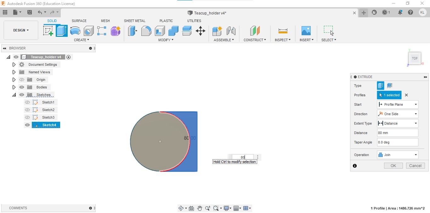
Step 5: Extrude the circle with a height of 5mm.

Step 6:Extrude the rest of the remaining part with a height of 80mm
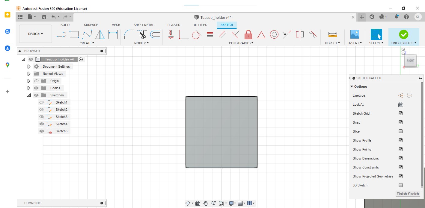
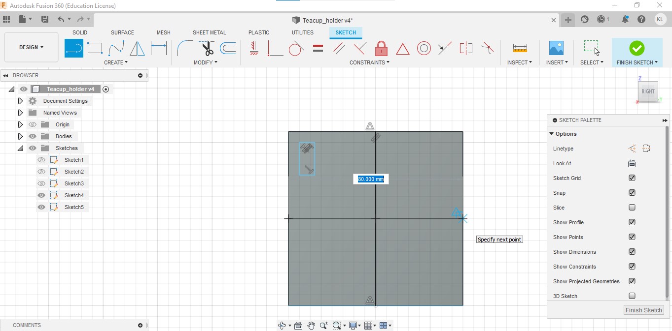
Step 7:Create a new sketch on the back surface of the tea cup holder
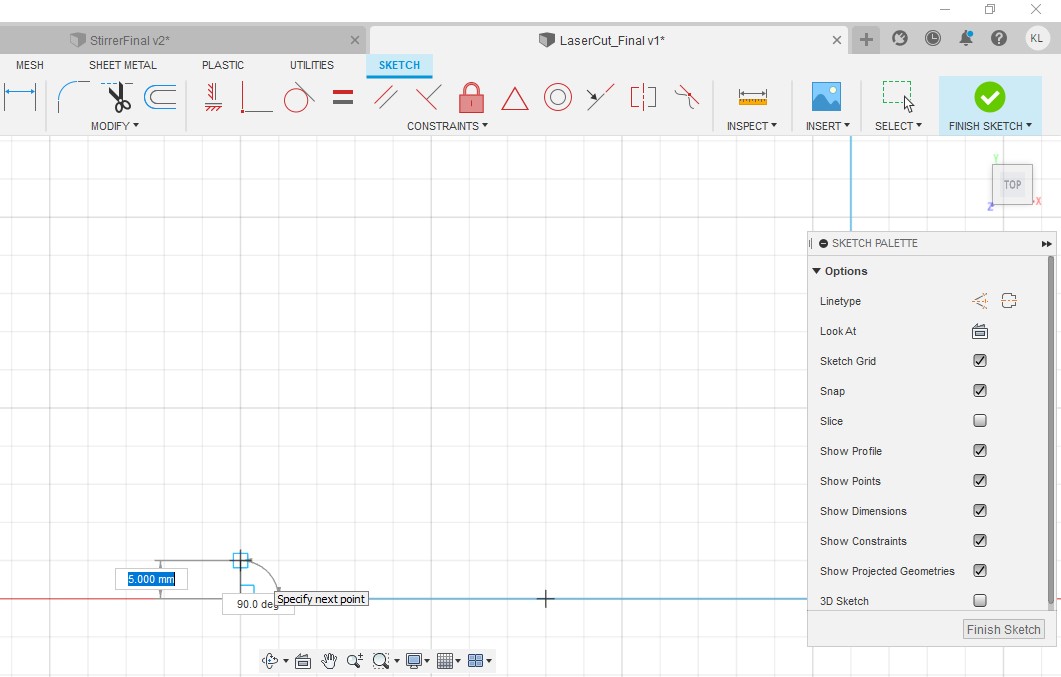
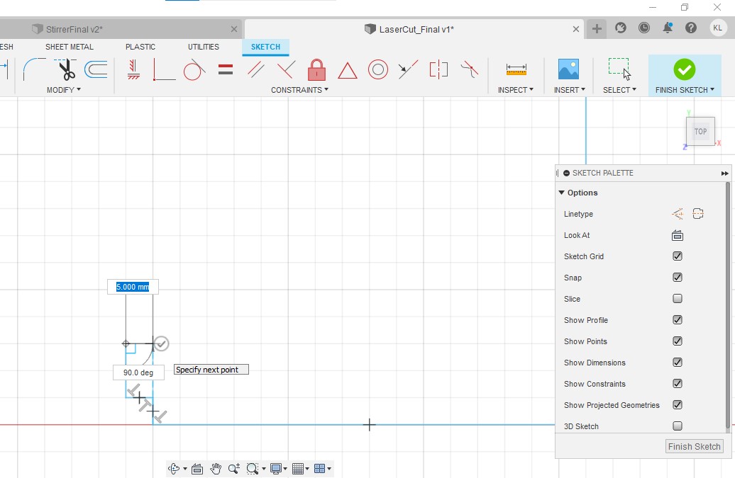
Step 8:Create a line with a length of 7mm.The line should have a gap of 5mm from both edges.
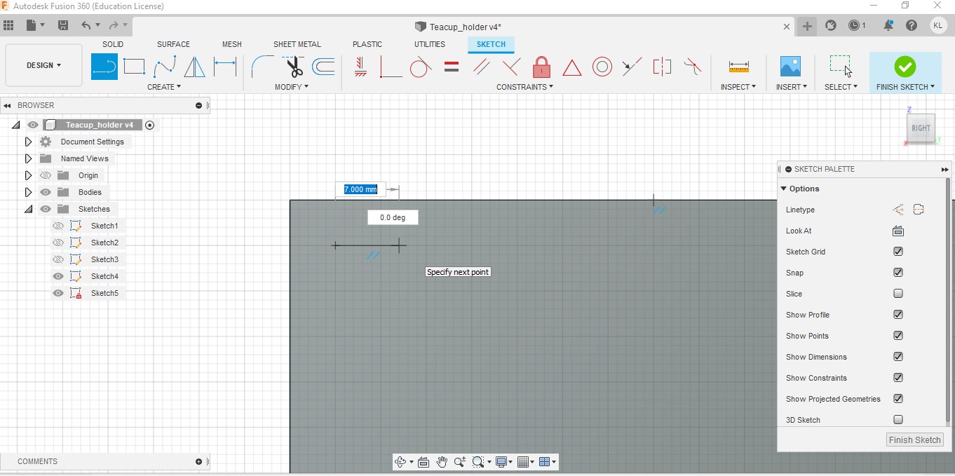
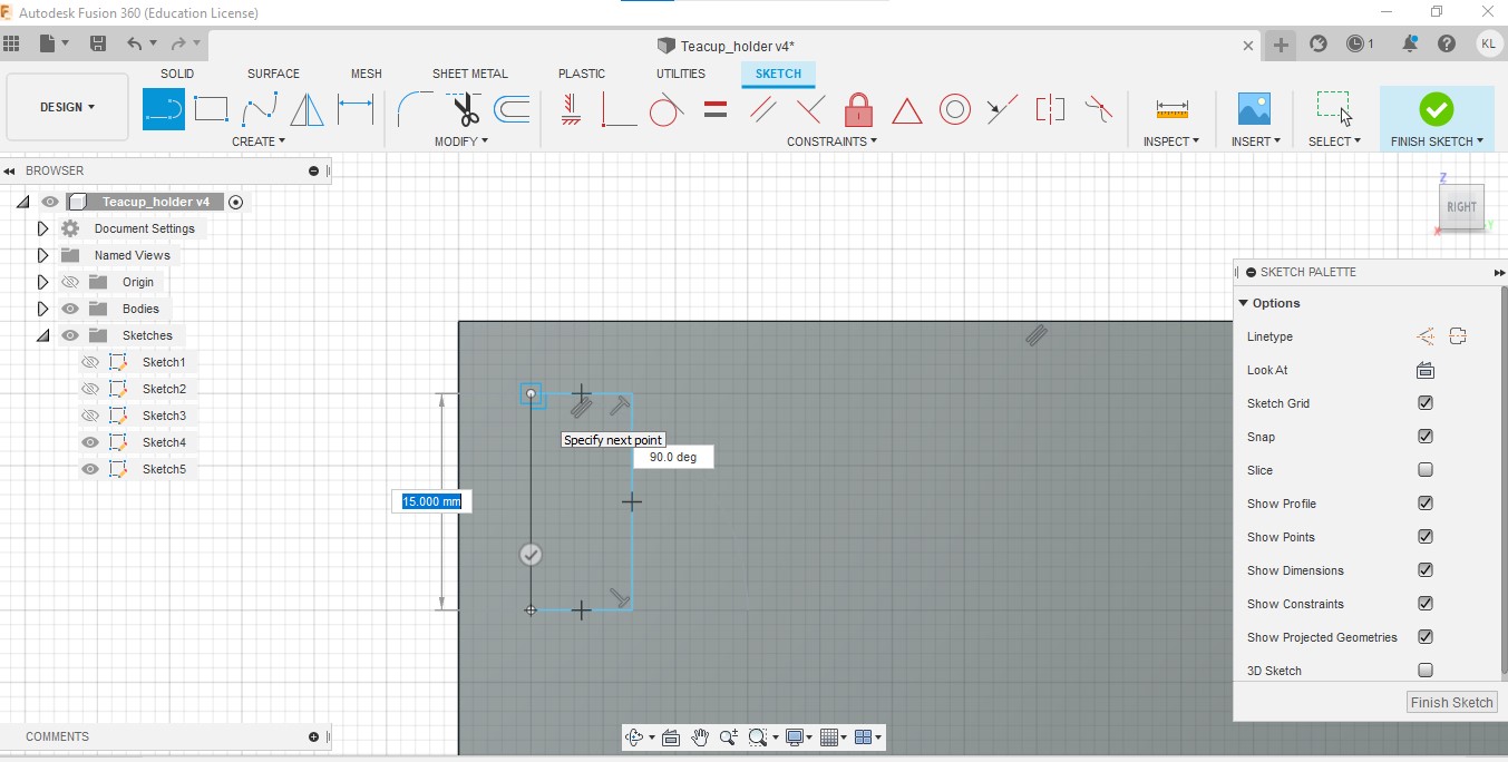
Step 9:Create another line with a length of 15mm and connect it with the line created in step 8

Step 10:Create a line with a length of 7mm and connect it with the line is step 9.

Step 11:Create a line with a length of 15mm to complete the rectangle.
Step 12:Draw a vertical line with a length of 80mm in the middle of the square.This will be used as our mirror line

Step 13:Draw a horizontal line with a length of 80 mm in the middle of the square.This will be used as our second mirror line.
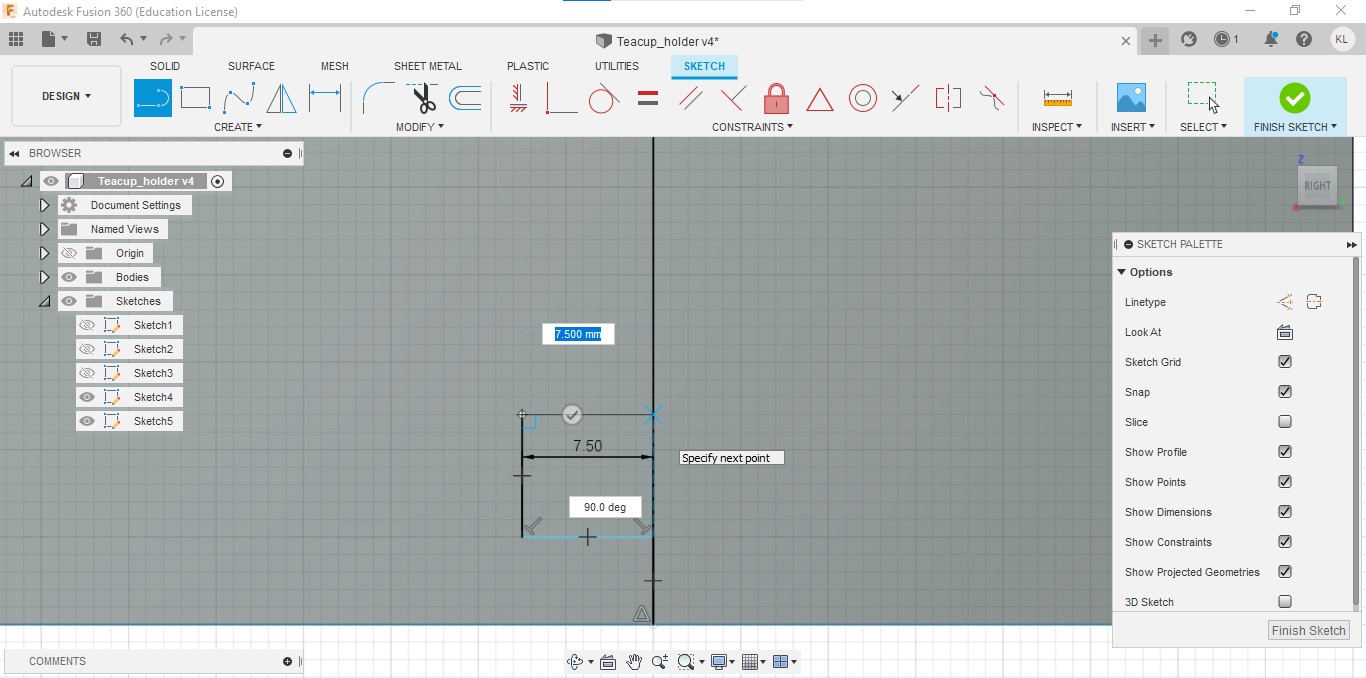
Step 14: 5mm above the centre of the vertical line, draw a line with a length of 7.5mm.

Step 15: Draw another line with a length of 7mm upwards and connect it to the line drawn in step 14.
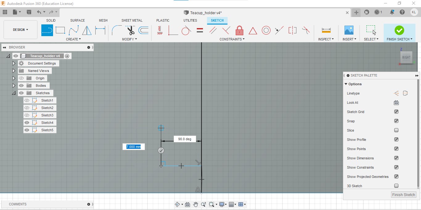
Step 16: Draw another line with a length of 7.5mm and connect it to the line drawn in step 15.
Step 17: Using the mirror function, we are going to mirror the first rectangle we created and use the horizontal middle line as out mirror line.

Step 18: Next mirror the 2 rectangles and 1 square on the left hand side and use the vertical middle line as our mirror line. After that click on finish sketch.

Step 19:Cut the holes that we just created by 5mm in step 18. With that, we have finished creating the tea cup holder.

Design and build of Stirrer (Done by Kieran)
Documentation of Stirrer

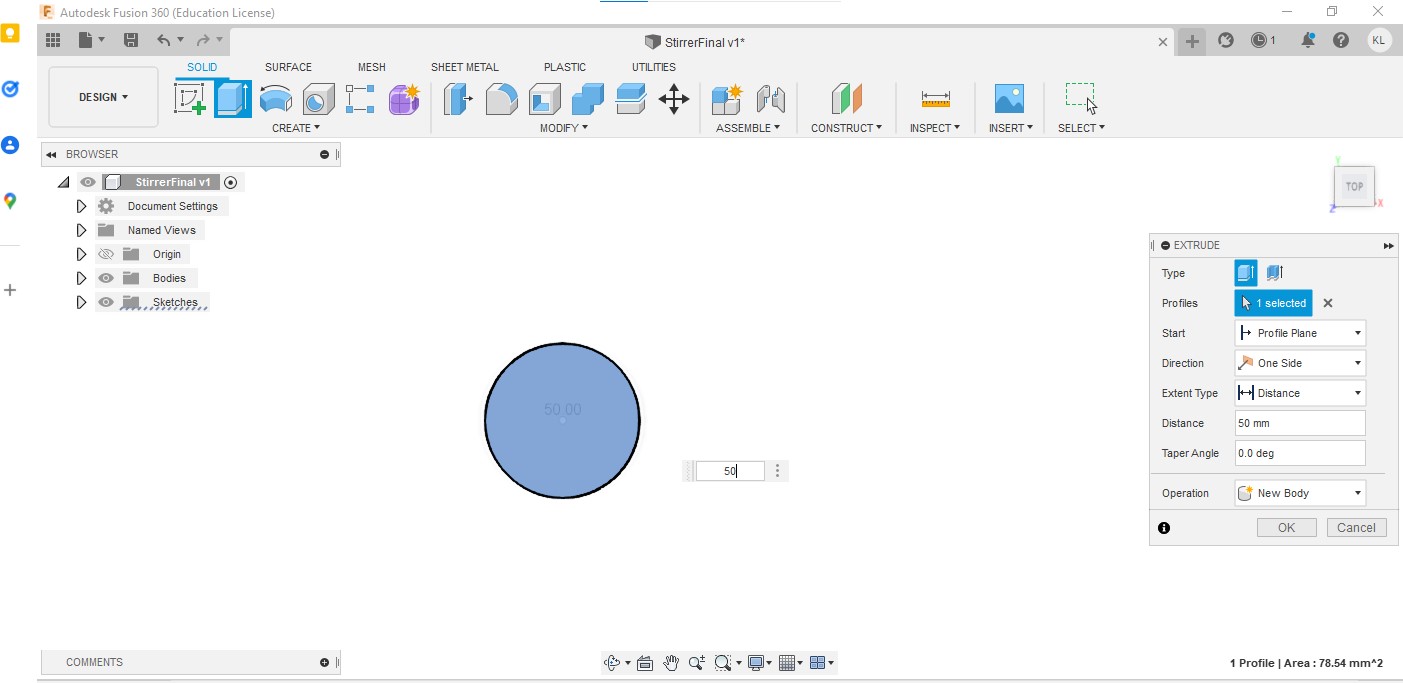
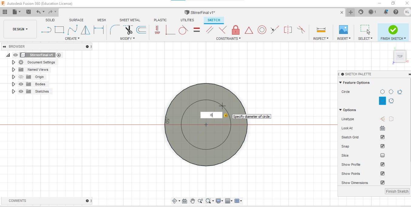
Step 1: First create a new sketch and create a circle with a diameter of 10mm.

Step 2:Extrude the circle with a length of 50mm.
Step 3:Create another sketch with a smaller circle with a diameter of 6mm. Extrude the smaller circle by a value of -5mm.
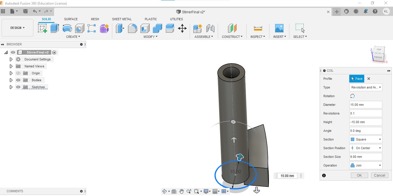
Step 4: At the bottom of the circle create a coil with a diameter of 10mm.

Step 5:Here are the settings for the coil
Diameter: 15mm
Revolution: 0.1
Height: -15mm
Section: Square
Section size: 9mm
Operation: New Body
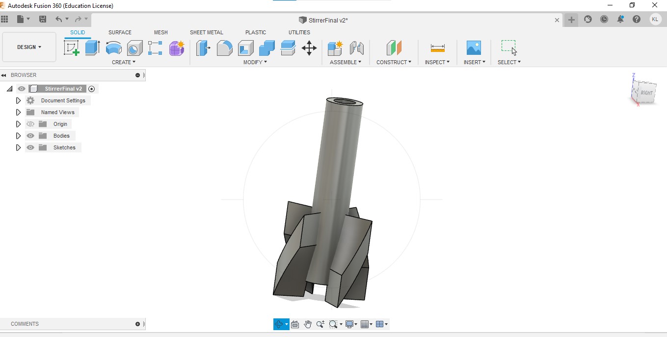
Step 6: Next, we will use the circular pattern tool and select our coil as our object and the cylinder as our axis.Change the quantity to 3.

Step 7:With that, the stirrer is complete.
Design and build of Laser Cut Pieces (Done by Kieran and Anwar)
Documentation of Laser Cut Pieces.
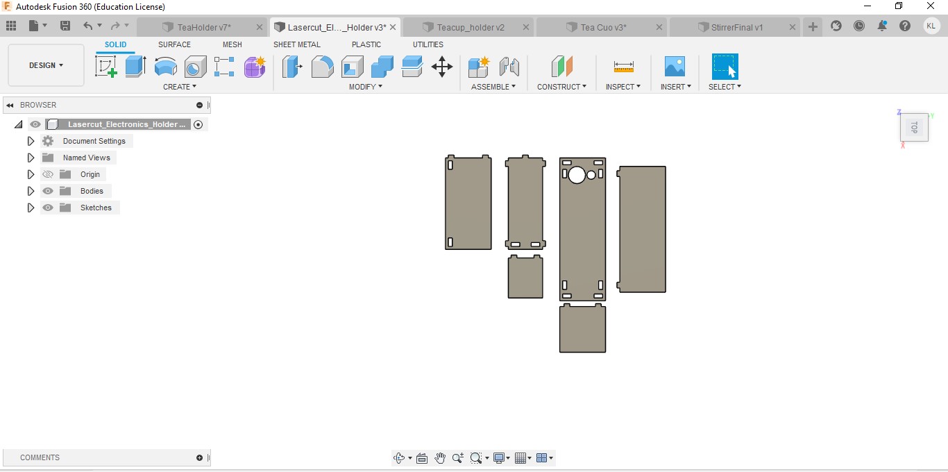
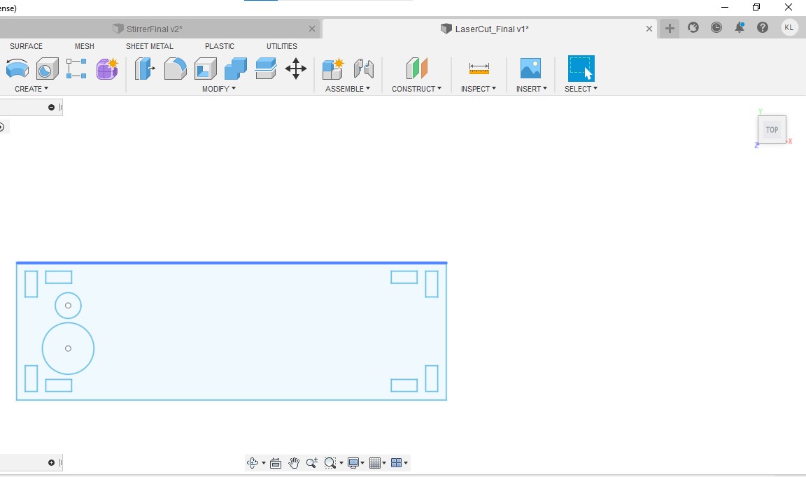
Electronics holder
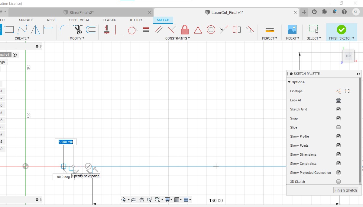
Step 1:Create a line with a length of 80mm

Step 2: Create another line with a length of 250mm and connect it to the line created in step 1.

Step 3:Make it into a rectangle with a breadth of 80mm and a length of 250mm.

Step 4:Create a circle with a diameter of 30mm.The two edges should be also 30mm away from the centre of the circle.

Step 5: Create another circle with a diameter of 15mm

Step 6:Create a rectangle with a length of 15mm and breadth of 7mm. The rectangle should be 5mm away from both the edges.

Step 7: Create another rectangle with a length of 15mm and 7mm. The rectangle should be 5m away from the horizontal edge and about 20mm away from the vertical edge.

Step 8: Next, create two middle line vertically and horizontally.

Step 9:NNext mirror the two rectangles we have created using the horizontal line as the mirror line.

Step 10:Mirror the 4 rectangles we have created in step 9 and mirror it using the vertical middle line.

Step 11:Remove both vertical and horizontal middle line.
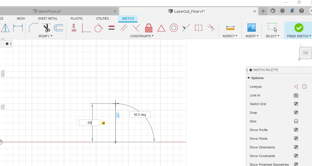
Step 12:Next create a vertical line of 80mm and a horizontal line with a length of 220mm.
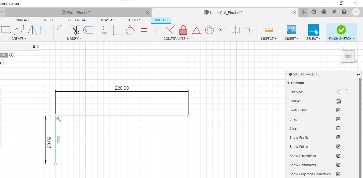
Step 13:Create another line with a length of 80mm vertically downwards.
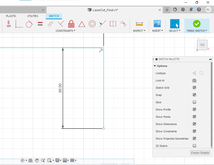
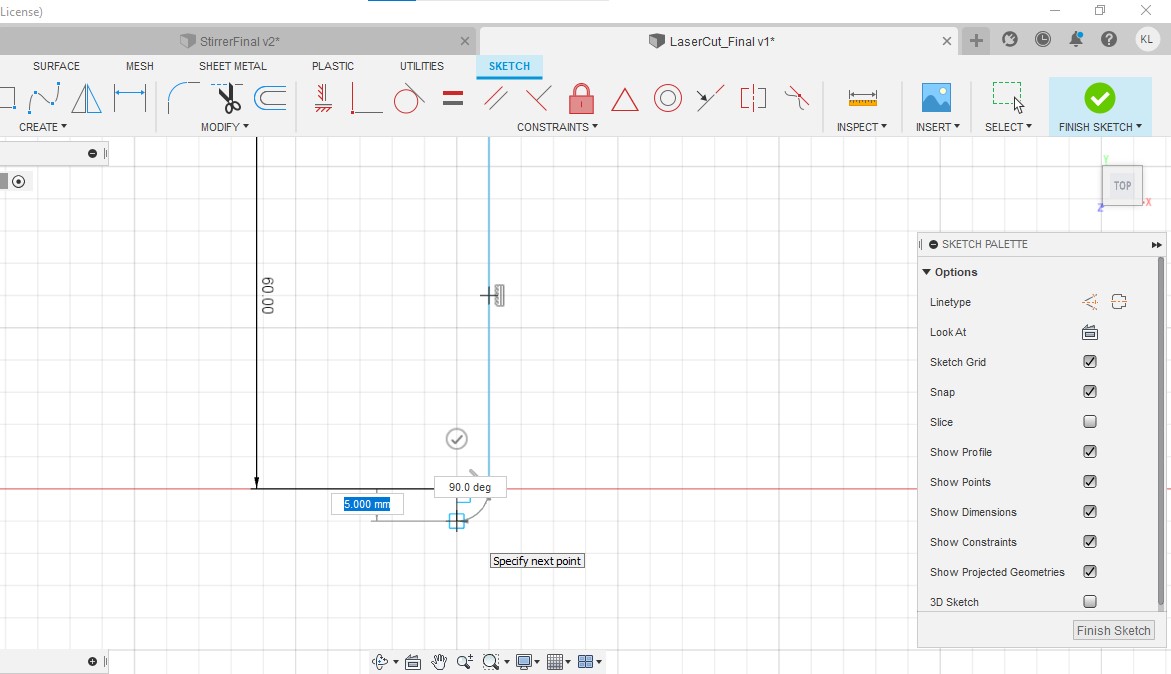
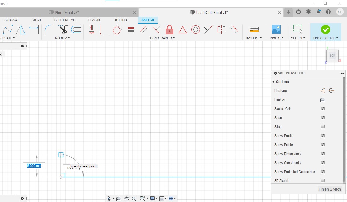
Step 14:Create a line 5 mm horizontally towards the left.
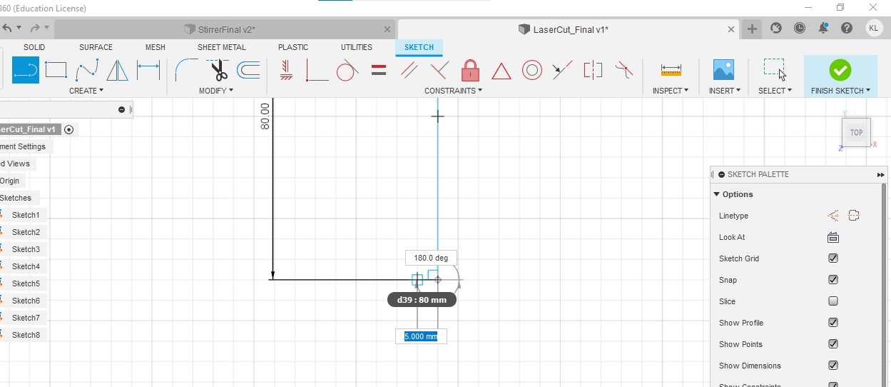
Step 15:Create another line with a length of 5mm

Step 16: Create a line with a length of 10mm.

Step 17:Create a line with a length of 5mm.

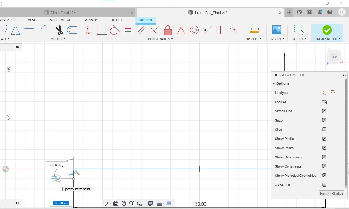
Step 18:Create a line of length 190mm. And repeat step 14-17 for the other end.

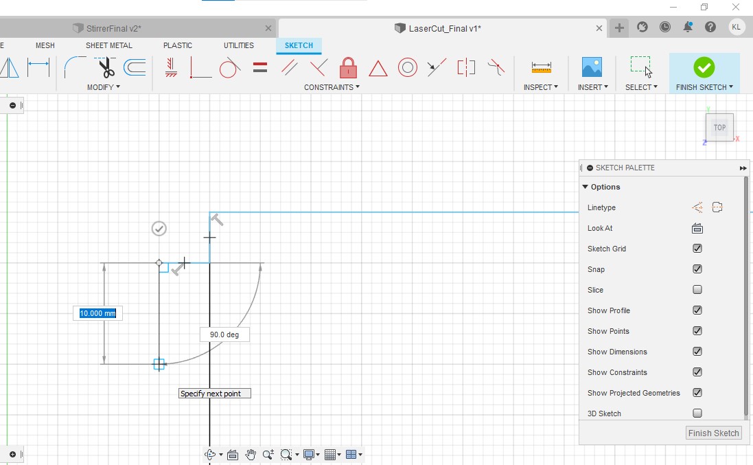
Step 19:Create a 3 lines each with a length of 80mm like the picture shown below.
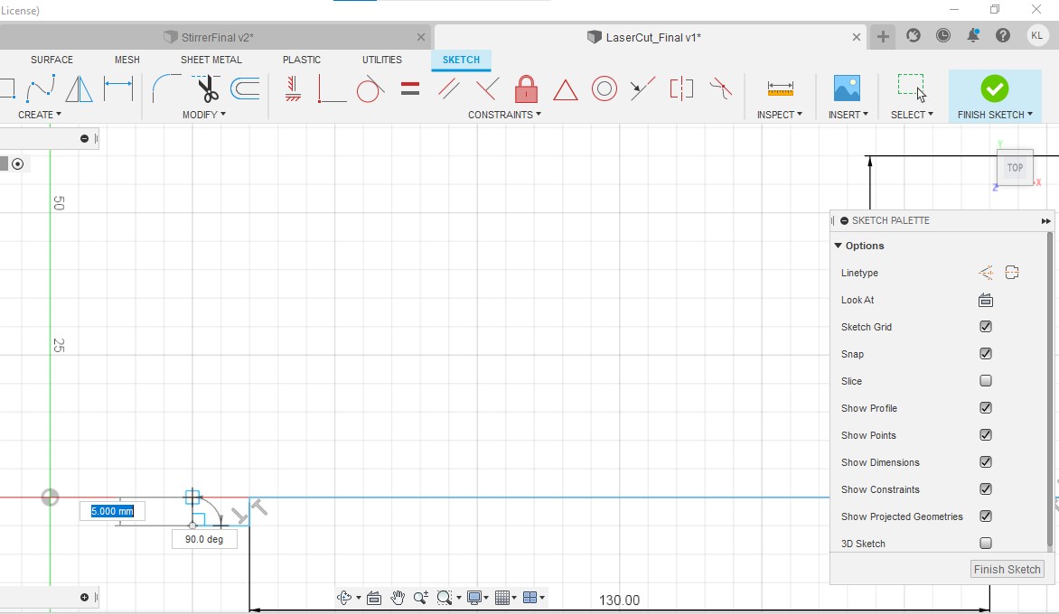
Step 20:Create a vertical line upwards with a length of 5mm.
Step 21:Create a line 5 mm horizontally towards the left.

Step 22: Create a line vertically upwards with a length of 10mm.

Step 23: Create a line horizontally towards the left with a length of 5 mm.
Step 24:Repeat step 20-24 on the other end and create a line with a length of 60 mm to connect them together.
Storage section
Step 1: Create a line with a length of 60mm
Step 2:Create a line 5 mm horizontally towards the left.

Step 3:Create a line 5mm downwards.
Step 4:Create a line 10mm horizontally towards the left.

Step 5:Create a line 5 mm vertically upwards.

Step 6:Create a line 130mm horizontally towards the left.

Step 7:Create a line 5mm vertically downwards.

Step 8:Create a line 10mm horizontally towards the left.
Step 9:Create a line 5mm vertically upwards.
Step 10:Create a line 5 mm horizontally towards the left.
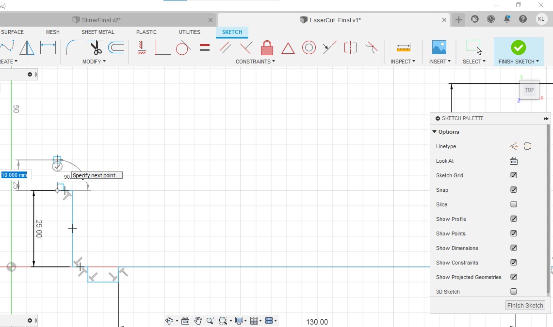
Step 11:Create a line 25mm vertically upwards.
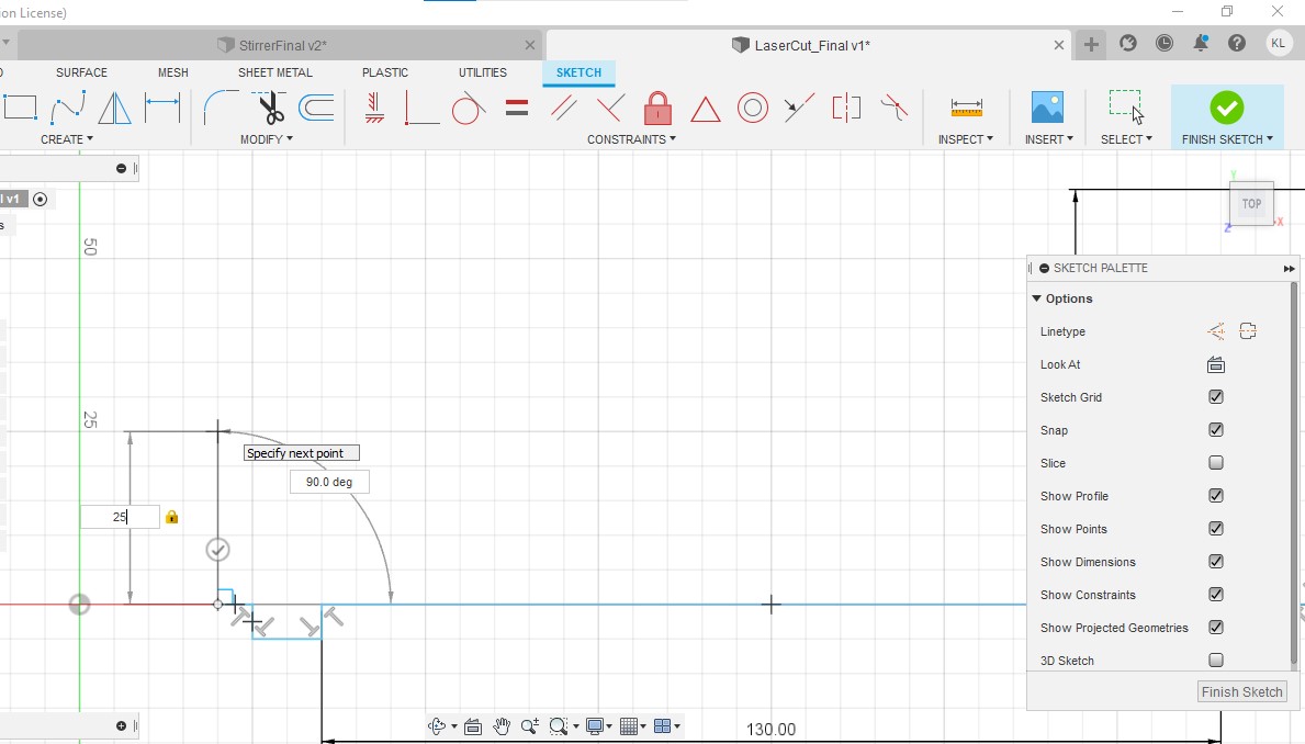
Step 12:Create a line 5mm horizontally towards the left

Step 13:Create a line 10mm vertically upwards.
Step 14:Create a line 5mm horizontally towards the right.

Step 15:Repeat Step 2 to 14 on the other side.The complete piece should look like this.

Step 16:Create a rectangle with a length of 15mm and breadth of 7mm.The rectangle should be 5mm away from both vertical and horizontal edges.

Step 17:Repeat the same for the rectangle below.

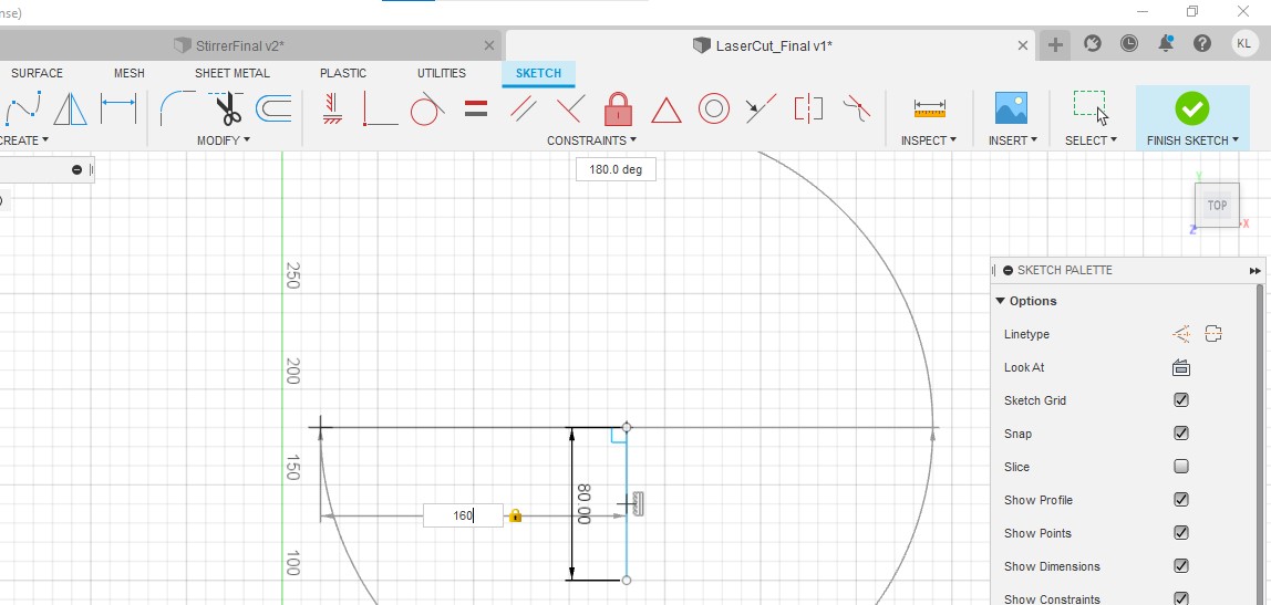
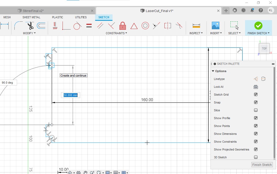
Step 18:Create a vertical line with a length of 80mm.

Step 19:Create a line of 160mm horizontally towards the left.
Step 20:Create a line 5mm vertically downwards.

Step 21:Create a line 5 mm horizontally towards the left.

Step 22:Create a line 10mm vertically downwards.
Step 23:Create a line 5mm horizontally towards the right

Step 24:Create another line 160mm long horizontally towards the left.

Step 25:Create a line 5mm vertically upwards.
Step 26:Create a line 5mm horizontally towards the left.

Step 27:Create a line 10mm vertically upwards.

Step 28:Create a line 5mm horizontally towards the right.

Step 29:Repeat Step 25-28 on the other end and use a line with a length of 60mm to connect it.
Step 30: Create a rectangle 5 mm away from both edges with a length of 15 mm and a breadth of 7mm.

Links to Teammate's blog
Design and Sketching of Tea Maker,Programming (Done by Nick)
Link to this Blog: https://cp5070-2021-2b01-group2-nick.blogspot.com/2022/02/project-development.html
Assembly of parts (Done by Anwar)
Link to his Blog: https://cp5070-2021-2b01-group2-anwar.blogspot.com/2022/02/project-development.html
Wiring (Done by Xavier) Link to his Blog: https://cp5070-2021-2b01-group2-xavier-chua.blogspot.com/2022/02/cpdd-blog-project-development.html
.
Final Product

This is how our final product looks when assembled together.There are still certain areas that can be improved to ensure our product looks nicer.
Problems and Solution
3D Printing:
Tray to hold electrical components was printed too small
Solution: Laser cut the tray instead
Joineries for 3D printed parts were wider than expected and did not fit through the holes
Solution: Design the holes bigger to allow extra space for joineries to fit in
Arduino wiring:
LCD Display did not work even though it was working fine before
Solution: Request for a new LCD Display once we found out it was spoiled
Wires disconnect easily, hindering our progress
Solution: Keep wires connected together as a bunch so that they do not come undone
Assembly of parts
Glue from gun glue was not meant to hold the acrylic pieces
Solution: Use acrylic glue
Not enough acrylic glue was applied, causing tea maker to fall apart
Solution: Reinforce the structure with more acrylic glue
Project Design Files
Combined Code Used
#include <Wire.h>
//I2C
#include <LiquidCrystal_I2C.h>
//OneWire bus suport
#include <OneWire.h>
//DS18B20 temperature sensor support
#include <DallasTemperature.h>
//DS18B20 sensor pin
#define ONE_WIRE_BUS 2
#include <Servo.h>
#include <pitches.h>
int buzzerpin = 8;
unsigned long timer1 = 119000; // 2 min
unsigned long timer2 = 179000; // 3 min
unsigned long timer3 = 239000; // 4 min
unsigned long timer4 = 299000; // 5 min
unsigned long TimeNow;
bool startbuzzer=false;
bool startedbuzzer=true;
bool startedbuzzer2=true;
bool startedbuzzer3=true;
bool startedbuzzer4=true;
// Setup a oneWire instance to communicate with any OneWire devices
// (not just Maxim/Dallas temperature ICs)
OneWire oneWire(ONE_WIRE_BUS);
// Pass our oneWire reference to Dallas Temperature.
DallasTemperature sensors(&oneWire);
Servo myservo; // create servo object to control a servo
// twelve servo objects can be created on most boards
int pos = 0; // variable to store the servo position
LiquidCrystal_I2C lcd(0x27,16,2); // set the LCD address to 0x27 for a 16 chars and 2 line display
// notes in the melody:
int melody [] = {
NOTE_C5, NOTE_C5, NOTE_C5, NOTE_C5, NOTE_C5, NOTE_C5, NOTE_C5, NOTE_C5
};
// note durations: 4 = quarter note:
int noteDurations [] = {
4, 4, 4, 4, 4, 4, 4, 4
};
void setup()
{
lcd.init();
lcd.backlight(); //Turns backlight on
sensors.begin();
myservo.attach(9); // attaches the servo on pin 9 to the servo object
startbuzzer = true;
// buzzer code (for loop)
}
void loop()
{
sensors.requestTemperatures();
//Read first sensor
float temp = sensors.getTempCByIndex(0);
//Print first sensor results
lcd.setCursor (0, 0 );
lcd.print("T: ");
lcd.print(temp);
lcd.print(" ");
// print the number of seconds since reset:
lcd.setCursor (2, 1 );
lcd.print(millis() / 1000);
//Wait 0.1 sec
delay(100);
for (pos = 0; pos <= 0; pos += 1) { // goes from 0 degrees to 180 degrees
// in steps of 1 degree
myservo.write(pos); // tell servo to go to position in variable 'pos'
delay(0); // waits 15ms for the servo to reach the position
}
for (pos = 0; pos >= 0; pos -= 1) { // goes from 180 degrees to 0 degrees
myservo.write(pos); // tell servo to go to position in variable 'pos'
delay(0); // waits 15ms for the servo to reach the position
}
unsigned long currentTime = millis();
if (startbuzzer){
TimeNow = currentTime;
startbuzzer = false;
startedbuzzer = true;
startedbuzzer2 = true;
}
if (startedbuzzer){
if((unsigned long)(currentTime - TimeNow >= timer1)){
buzz();
startedbuzzer = false;
}}
if (startedbuzzer2){
if((unsigned long)(currentTime - TimeNow >= timer2)){
buzz();
startedbuzzer2 = false;
}}
if (startedbuzzer3){
if((unsigned long)(currentTime - TimeNow >= timer3)){
buzz();
startedbuzzer3 = false;
}}
if (startedbuzzer4){
if((unsigned long)(currentTime - TimeNow >= timer4)){
buzz();
startedbuzzer4 = false;
}}
}
void buzz(){
// iterate over the notes of the melody:
for (int thisNote = 0; thisNote < 8; thisNote++) {
// to calculate the note duration, take one second divided by the note type.
//e.g. quarter note = 1000 / 4, eighth note = 1000/8, etc.
int noteDuration = 1000 / noteDurations[thisNote];
tone(8, melody[thisNote], noteDuration);
// to distinguish the notes, set a minimum time between them.
// the note's duration + 30% seems to work well:
int pauseBetweenNotes = noteDuration * 1.30;
delay(pauseBetweenNotes);
// stop the tone playing:
noTone(8);
}
}
Stirrer
Tea Leaves Holder

Comments
Post a Comment